Shrink Sleeve Artwork Pre-Distortion for Bottle Contour
How shrink sleeve artwork is stretched before printing so it reads right once it grips the bottle — the prepress data flow, TD/MD role, and shrink proofing.
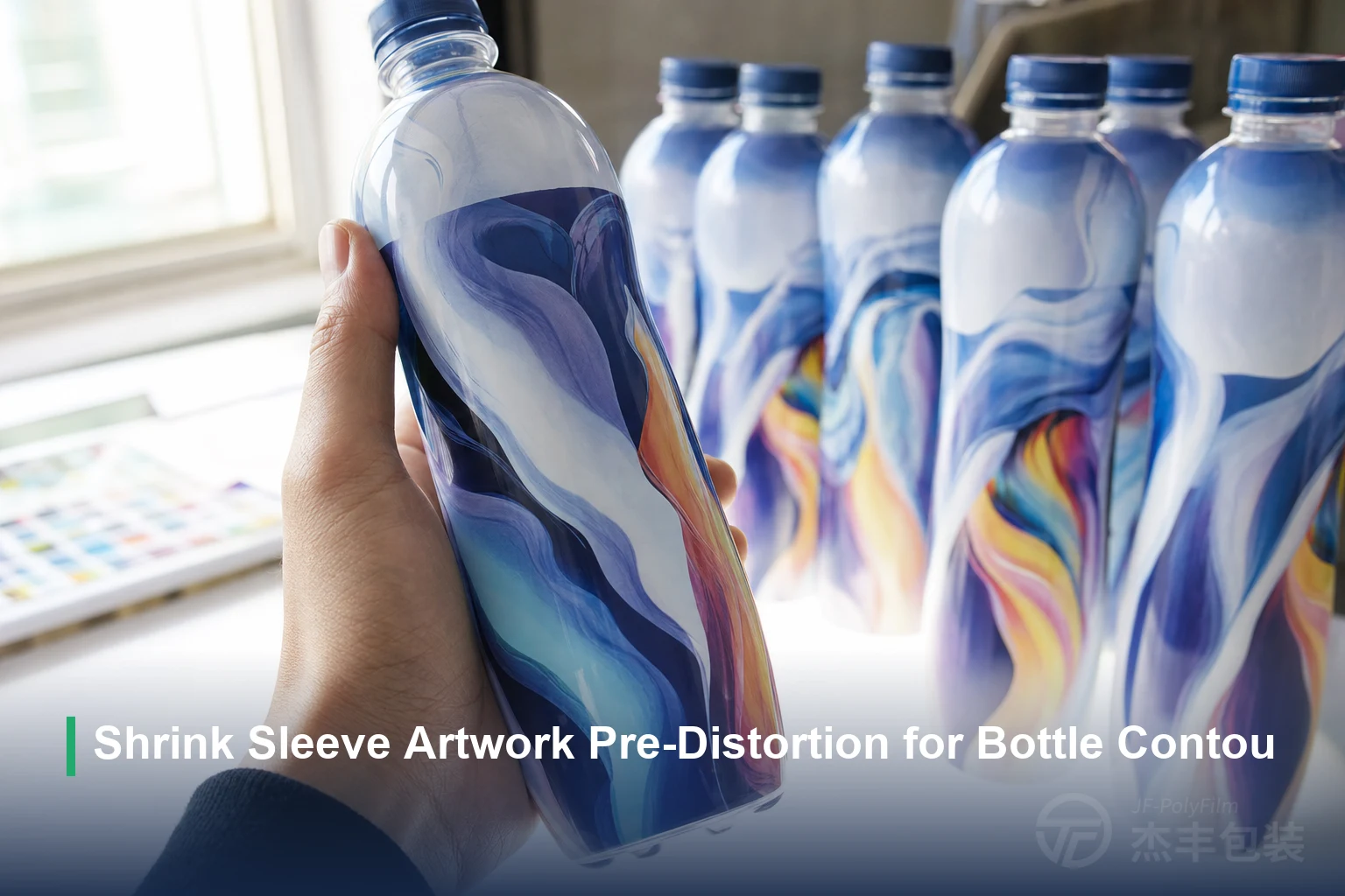
Shrink sleeve artwork pre-distortion is the prepress step that stretches a flat-film design in reverse — by the amount each part of the bottle will pull in — so the image snaps back to correct proportions once the sleeve grips the container. The file that looks distorted on-screen is the one that reads right on the shelf.
Key takeaways
- Compensation runs almost entirely around the bottle: a high-TD, low-MD film (JFPolyFilm’s clear grade holds TD ≥75% with MD ≤3.0%) tightens sideways while the sleeve barely shortens, so the map stretches the artwork circumferentially, not vertically.
- Distortion concentrates where the diameter changes fastest — shoulder, waist, neck, grip, and any sharp curve transition — while straight panels move little.
- The map is measured, not guessed: a grid film is sleeved onto the real container and shrunk, and the movement of each square sets the local stretch.
- Change the shrink rate (65/75/80%) or the resin grade and the compensation amount changes with it, so the distortion grid has to be rebuilt from a new test sleeve.
- Proof on batch-consistent film — five-meter-per-batch sampling with a COA anchors the shrink figures the map was built on — and orient barcodes as ladders off the high-shrink zones.
Why shrink sleeve artwork must be pre-distorted
The core reason is a dimensional mismatch: the graphic is printed flat but has to read on a curved, tapered, three-dimensional bottle. A shrink sleeve is a printed tube that is heated until it draws 360° around the container, so a design that is sharp and square on the flat web — the continuous roll of film as it prints — is forced onto a surface it was never sized for. Where the film contracts to follow that surface, a graphic printed at final proportions is dragged out of shape — letters compress, circles turn oval, straight rules bow.
Pre-distortion answers the mismatch before printing rather than after. The design is deliberately deformed in the opposite direction to the shrink, so that the contraction pulls it back into the intended shape instead of away from it. This is why a flat pre-distorted proof looks wrong on purpose: the on-screen file is stretched exactly where the film will later pull in, and only the finished, shrunk sleeve shows the artwork as designed. Getting that reverse-map right is a prepress discipline; how the compensated file is then physically printed — gravure, flexographic, or digital — is a separate decision covered in PET shrink sleeve printing methods.
Where distortion comes from: the bottle contour
Distortion is rooted in one geometric fact the designer controls: the sleeve is sized as a flat tube to clear the bottle’s largest diameter, then shrinks down to every smaller diameter above and below it. The contraction the film must deliver at any height is the gap between that oversized starting circumference and the local diameter there — so the tighter a zone is relative to the widest point, the more the film pulls in and the more it distorts whatever is printed on it.
That is why distortion is not spread evenly over the label — it tracks the bottle’s profile, concentrating wherever the diameter changes over a short vertical distance. Because the film has to contract more to wrap a narrowing neck or a swelling waist than to cover a straight panel, the local shrink is highest exactly at those transitions, and so is the deformation of anything printed across them. A cylinder of constant diameter would barely distort at all; a contour bottle distorts most at its sharpest curves and transitions.
Mapping the artwork therefore starts from the geometry. Reading the container as a stack of diameters up its height shows where the film will work hardest and where the compensation must be largest.
| Bottle zone | Distortion risk | Prepress countermeasure |
|---|---|---|
| Shoulder / taper | High — fast diameter change squeezes graphics vertically | Add the most reverse-stretch here; keep small type and fine images off it |
| Waist / curve transition | High — the film pulls in sharply, waving straight lines | Map the local shrink precisely; favor abstract shapes over rigid rules |
| Neck | High — smallest diameter, largest draw | Avoid critical copy; let background carry the zone |
| Grip / handle recess | High — compound curvature in two directions | Keep logos and codes clear of it; test-fit before committing |
| Seam overlap | Moderate — double film thickness, alignment tolerance | No small type or continuous pattern across the seam |
| Straight body panel | Low — near-uniform diameter, little movement | Place barcode, key copy, and registration-critical art here |
The container’s base geometry also decides how cleanly the sleeve settles: a bottle with a radiused base lets the film lock onto the body, while a straight-walled base gives the film nothing to grip and lets the bottom edge flag up and out. Both are read into the map so the artwork is not anchored to a zone the film cannot hold steady.
How TD and MD shrink decide the direction of compensation
The compensation runs mostly in one direction because the film shrinks mostly in one direction. Transverse shrink (TD) is the working axis — it tightens the film sideways around the circumference — while machine-direction shrink (MD) stays low so the sleeve does not shorten vertically and pull the artwork out of registration. Pre-distortion is therefore overwhelmingly a circumferential stretch: the design is lengthened around the tube by the local TD figure at each height, with only a small vertical correction.
JFPolyFilm’s clear and white PETG grades run TD ≥75% with MD ≤3.0%, and that split is what makes the compensation direction clean — nearly all the movement is horizontal, so the map has a dominant axis rather than a tangle of two large corrections. A high MD would force a second large vertical stretch and complicate registration; holding MD low keeps the reverse-map predictable. How much TD the container actually needs depends on its curvature, which is the separate question of choosing a shrink rate of 65, 75, or 80%.
Building the distortion map: from bottle profile to pre-distorted grid
The map is built from measured shrink, not estimated from the bottle drawing. The reliable route is a grid test: a regular pattern of squares is printed on the actual production film, sleeved onto the real container, and run through the shrink tunnel at the target temperature. As the film draws down, each square deforms by the local shrink at its height, and the shrunk sleeve is then scanned or measured square by square to record how far and in which direction the film pulled at every point on the contour — a captured measurement, not a visual estimate.
Building that grid depends on the container data prepress is handed, so the deliverable matters. The most reliable handoff is a physical sample of the exact production container plus a dimensioned drawing giving the outside diameter at each height, the target layflat width of the sleeve, and whether the bottle is proofed filled or empty — enough to sleeve a real grid rather than infer shrink from a flat drawing.
That measured grid becomes the template, and the warp is a direct inverse. Where the film will pull a zone in to a narrower width, the artwork in that zone is drawn proportionally wider by the same amount, so contraction returns it to its intended size rather than shrinking it below it; a zone that barely moves is left nearly untouched. Modern prepress distortion tools carry this data flow — building a virtual grid, applying the reverse-warp, and previewing the shrunk result — but the principle is independent of any particular software: profile the container by diameter at each height, derive the local stretch, warp the artwork onto the grid, then confirm on a physical proof. The film’s freedom from corona pre-treatment helps here, since JFPolyFilm grades print directly by gravure, flexographic, or digital with no added surface step that would introduce another variable between the grid and the finished print.
How shrink rate and grade change the compensation amount
A distortion map is valid only for the exact shrink behavior it was built on, so changing the film changes the map. Because compensation is tied to how much the film pulls in, moving between the 65%, 75%, and 80% shrink rates JFPolyFilm offers alters the contraction at every height and therefore the stretch the artwork needs — a grid built for one rate over-corrects or under-corrects for another. The same is true across resin grades: JFPolyFilm’s CPET grade runs TD 74±2%, a different figure from the ≥75% of clear PETG, so switching grade for a recycling or optical reason resets the compensation.
The practical rule is that a shrink-rate or grade change is a re-test, not a tweak. A new grid sleeve is run on the target container, the local shrink is re-measured, and the map is rebuilt before the artwork is re-warped — which is why the film decision and the artwork decision are locked together early. Selecting the grade itself, weighing clear against white, CPET, or RPET, is set out in clear vs white PETG; the point for prepress is that whichever grade wins, its shrink figures become the input the map is built from, and a batch’s COA shrink data is the anchor for that input.
Proofing: grid sleeves, short runs, and COA cross-check
No pre-distortion is trusted until it is proven on the real container, so the map is validated by a physical shrink trial before any volume runs. The grid sleeve confirms the geometry — where the film grips, where it pulls hardest, where it wants to flag (lift away from the container at an unsupported edge) — and a short printed run then shows the actual artwork behaving as the map predicts, with type, logos, and gradients landing in proportion after the tunnel. Judging that proof is a measured step, not an eyeball call: overlay the shrunk sleeve against the intended layout to catch drift, check type height and logo proportion at the shoulder and waist where distortion is worst, confirm straight rules have not bowed, and run the printed barcode through a verifier to a pass grade rather than trusting that it looks fine. Tolerances from print, folding, seam placement, and container variation stack up, so the proof is planned against the worst case rather than the nominal one, and the loop is not skipped to save a cycle.
The proof is only meaningful if the film in the trial matches the film in the production run. JFPolyFilm samples each batch at five meters or more and runs the full property set — shrinkage rate, thickness, haze, tensile strength — and issues a COA with the shipment, so the shrink figures the map was built on stay consistent from proof to production and batch to batch. A drifting shrink rate between batches would quietly invalidate a map that proofed correctly, which is why batch-consistent film and its COA shrink data are part of the prepress chain, not just a quality formality. Where a proof still shows shrink faults — wrinkling, flagging, or uneven draw from the tunnel side rather than the artwork side — those are process problems addressed in solving PETG shrink film problems.
Common pre-distortion failures and how to avoid them
Most on-shelf distortion faults trace back to a handful of predictable causes, each with a prepress or layout fix.
| Failure on the bottle | Where it comes from | How to avoid it |
|---|---|---|
| Type waves or compresses | Copy sits on a high-shrink shoulder or waist, under-compensated | Keep small type on flat panels; add stretch where the grid showed most movement |
| Barcode won’t scan | Bars smeared or pinched by circumferential shrink | Print the code as a ladder — bars stacked so shrink runs along their length, not across their widths — on the flattest panel, off the seam and high-shrink zones |
| Gradient or color band misaligns | Continuous tone crosses a fast diameter change | Break long gradients away from transitions; avoid patterns that span the seam |
| Logo skews or ovals | Element placed on compound curvature (grip, neck) | Move it to a low-shrink zone; use abstract shapes that tolerate small movement |
| Pattern breaks at the seam | Continuous artwork run across the overlap | Design a deliberate seam; no fine detail or critical copy across it |
The through-line is to route registration-critical art toward the low-shrink panels and let the high-shrink zones carry forgiving elements. Curved and abstract graphics absorb a little movement invisibly where rigid rules and fine type expose it, and a dark bottle behind a light film exaggerates any shift, so a design that hides tolerance rather than advertising it survives the shrink best.
A film that carries its own shrink credentials makes accurate pre-distortion easier to hold. JFPolyFilm’s clear PETG shrink film prints direct in three shrink rates with a COA per batch, so the map is built on measured, repeatable figures rather than assumed ones.
Frequently Asked Questions
What is pre-distortion in shrink sleeve artwork?
Why does shrink sleeve artwork distort on a bottle?
How is a shrink sleeve distortion grid made?
Does the shrink rate of the film change the pre-distortion?
Why are barcodes printed sideways on shrink sleeves?
Related Articles
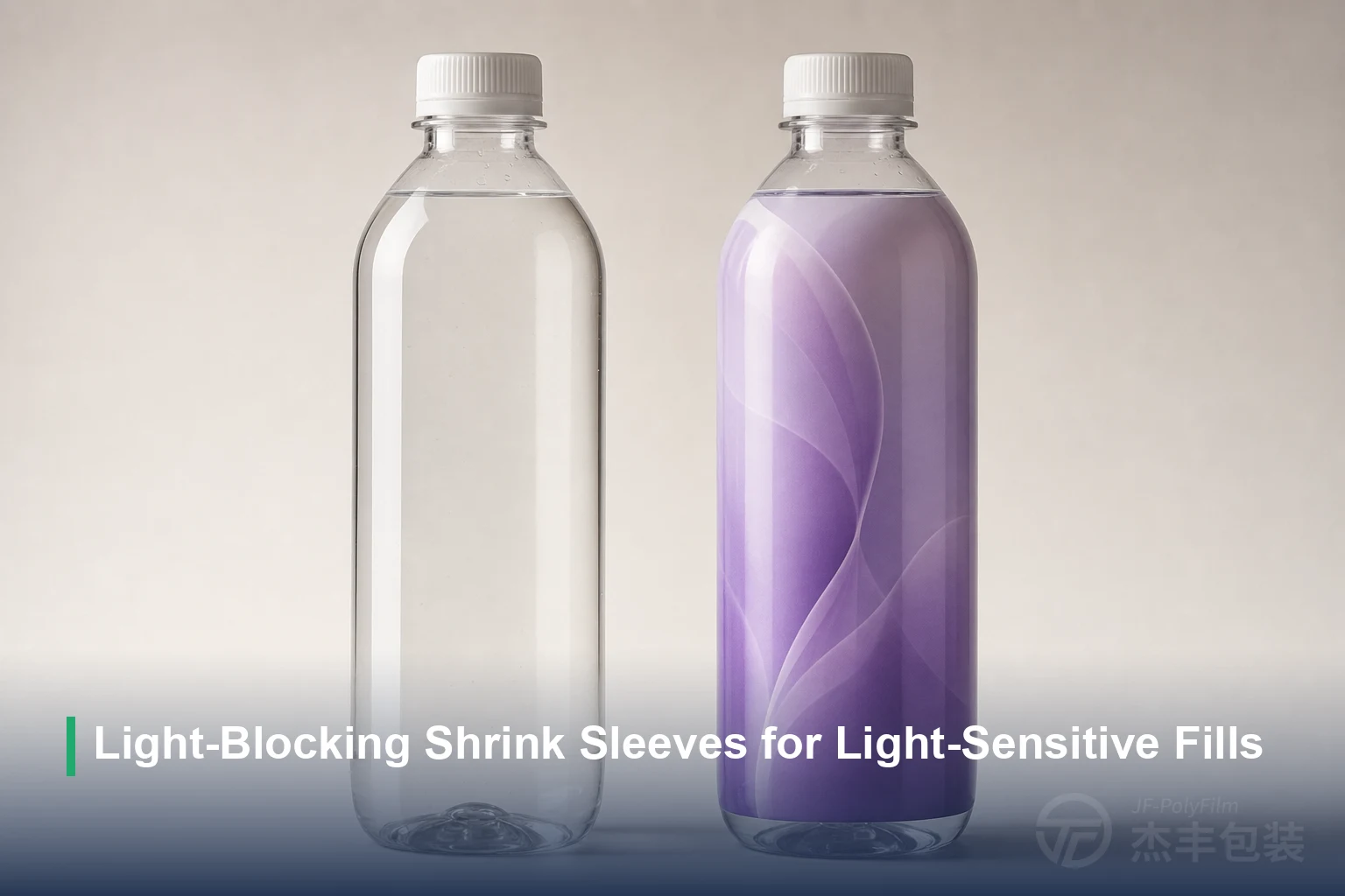
Light-Blocking Shrink Sleeves for Light-Sensitive Fills
Beer, dairy, supplements, and some medicines degrade under light. Which fills need protection, and how a full-body opaque PETG sleeve wraps the whole container to keep light off the contents.

Plastic Packaging Tax and Shrink Film: The 30% Rule
How plastic packaging taxes in the UK, Spain, Italy and the EU treat shrink sleeves, why the 30% recycled-content threshold is the number worth remembering, and how RPET film helps a sleeve cross it.
Need Expert Advice on Shrink Film?
Our technical team can help you choose the right film for your application.
Contact Us